Bring up Pro/ENGINEER as discussed in previous tutorials.
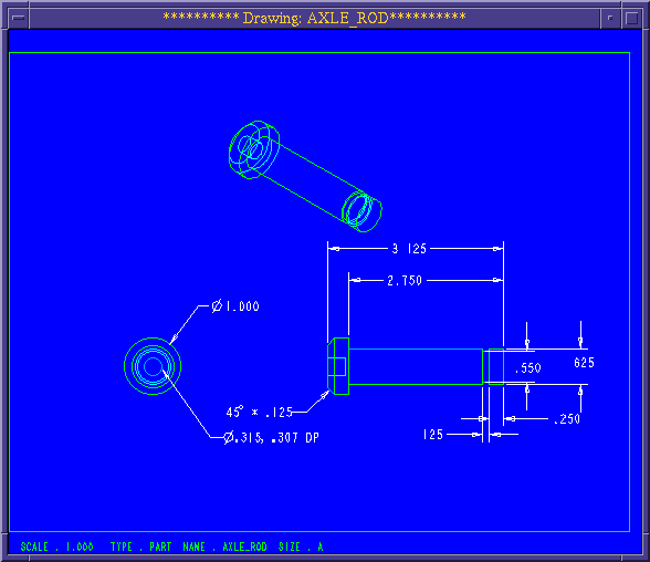
Using techniques learned in previous tutorials, create the following parts:
Note: Carefully evaluate the features on each part and identify lines of symmetry. Draw profiles and constrain based on the symmetry of the parts.
Note: Because of the number of parts involved, it would be best to create a separate directory for all the files created for this assembly. Go out to the desktop and create a new directory, tutorial5. Next, go back to Pro/E and use Misc>Change Dir to change to this directory. Now create your parts. Save each part as an individual file with the name given at the top of the drawing window shown in the figures.

Figure 1a.
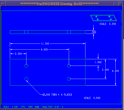
Figure 1b.
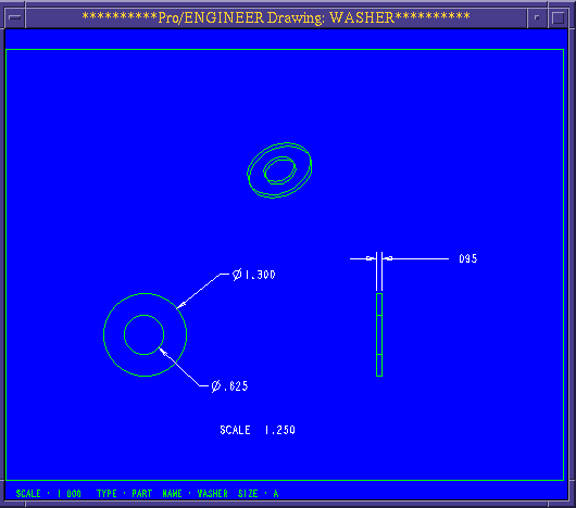
Figure 2a.
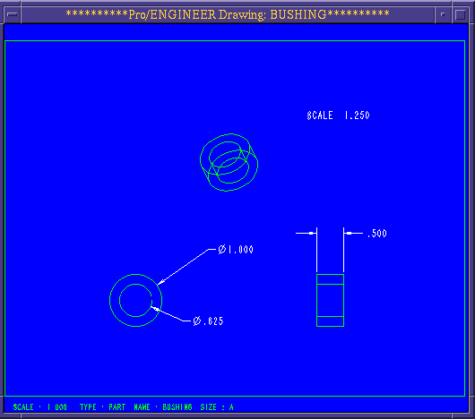
Figure 2b.
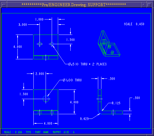
Figure 3.
The first five parts used in the assembly are complete. Save the parts and then close the windows to these parts as needed to reduce clutter on the screen. We will now advise you on the construction of next part, the pulley.
The first part will be a pulley. To begin create a circular disc with the following dimensions.
Use the default datum planes. Use the both sides command to extrude the disc.
diameter = 4
depth = 1
We will now use the revolved cut to create a groove in the pulley.
create>solid>cut>revolve | solid | done>one side | done
Pick a sketch plane that is perpendicular to the flat face of the disc.The reference plane will be the other datum plane perpendicular to the flat face of the disc.
In the sketcher mode, create a groove like the one seen in Figure 4.
First, create a horizontal centerline on the horizontal datum to represent the axis of rotation. Align the centerline.
Next, use a vertical centerline to constrain the "V" groove centered about the thickness of the disk. Make sure that you align the centerline to the datum.
Finally, draw the "V". Be certain that you align the endpoints of the "V" to the perimeter of the disc and the vertex of the "V" to the centerline. Regenerate, and complete the feature, revolving the cut 360 degrees.
"WARNING: Not all open ends have been explicitly aligned."
It is just a warning. It will not prevent you from performing the operation you desire.
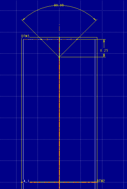
Figure 4.
We will now perform a protrusion to create the hub in the center of the disc (see Figure 5). We will actually place the profile in the middle of the disc on the center datum and extrude on two sides.
create>solid>protrusion>extrude | solid | done>two sides | done
The hub will have the following dimension:
diameter = 0.75
depth = 1.5
See Figure 5.
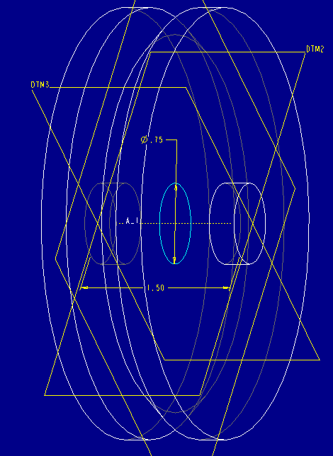
Figure 5.
You will now perform a hole all the way through the hub. Create the hole much like the hub was created. You can used the center datum again and cut the hole both sides. The diameter of the hole is:
diameter = 0.625
To reduce the weight, we are going to make some recess cuts on each side of the pulley.
create>solid>cut>revolve | solid | done>one side | done
The section profile should look like Figure 6a. Use a two centerlines as did for cutting the "V" groove, make sure to draw the horizontal centerline for the axis of rotation first. You can draw a rectangle on the right side first and then use Geom Tools>mirror to copy to the other side of the vertical centerline. Creating the rectangle on the left side this way means that you do not have to dimension the left rectangle and that changes in dimensions on one side will translate directly to the other.
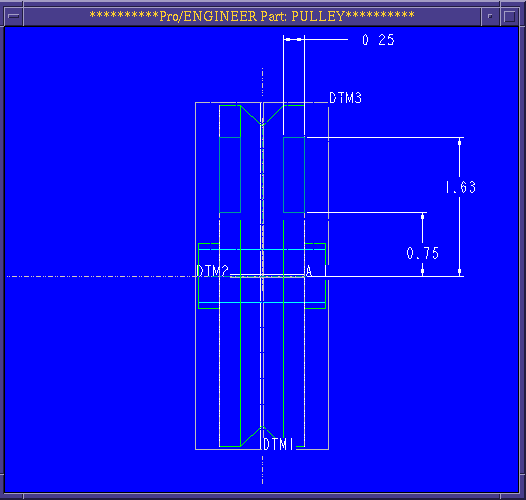
Figure 6a.
The part is finished now. It should look like Figure 6b. You should now save this part.
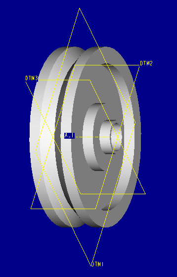
Figure 6b.
Now create a new part, the bolt, which will join the support with the base. The specifications for the bolt are:
1/2 - 20UNF x .875 long hex head bolt
We will start by creating the six sided, (hex) head of the bolt. Refer to your engineering graphics text for tables of standard fastener sizes. The appropriate table of Hex Cap Screws (bolts) will give the necessary dimensions.
NOTE: The threads on this part do not need to be created in order to save time and disk space. You should, however, create the chamfer on the hex head.
For creating the hexagon profile, the two perpendicular lines of symmetry can be used to simplify construction. Begin by creating centerlines aligned to the two datums. Next, draw just one angled side of the hexagon, mirror this about one centerline and then both angled lines about the other centerline. Draw in the last two sides. You can now constrain with one angle and two across-the-flats dimensions.
Finish the bolt with a shaft, chamfering the top of the hex head (Note: you can not use the chamfer command to do this chamfer.) and chamfering the bottom of the shaft. The completed bolt is shown in Figure 7.
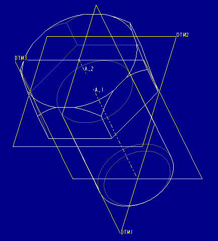
Figure 7.
After you save the finished bolt, start to putting the assembly together.
Go to the Assembly mode, in the mode menu.
create>Enter wheel_supp
First you will want to put in the base part of the assembly. Most other parts should attach to this main part. In this case it should be, appropriately, the base part. To enter this part, the commands are:
component>assemble>Enter base
The component menu will then appear. It is from this point that you will start to gather the individual parts.
Now you will want to bring in next parts.
assemble> Enter support
Notice that two other windows open at this point. One window, the component placement window, helps track the progress of constraining the new part (component) into the assembly. The other window is the part window of the part you are bringing into the assembly. The first thing you will want to do is click on the in assembly check box so that you can constrain the new component in the assembly window, rather than having to switch back and forth between the part and assembly windows.
In order to bring in another component, it must be constrained to the initial part. Even though you can see the lid in the assembly window, it will not stay there if you clicked on done at this point. Constraining is done through two primary types:
These two options, plus others, are found in the Place menu.
We will start with a mate.
Click on the mate button.
You will then click on the surfaces of each part that you wish to join. You will want to click on the top flat surface of the base, and the bottom surface of the support. This constraint constrains movement in one dimension.
Constrain movement in the other two dimensions by aligning the holes:
Click on the align button.
You will then click on the centerline of a hole on both the support and the base. This will ensure that they have coincident axes. Repeat for the other hole.
The prompt line now reads:
The component can now be placed.
This indicates that the two parts are fully constrained. The axis alignment constrained movement in the other two dimensions.
Pick done on the Comp Place menu.. The result is seen in Figure 8.
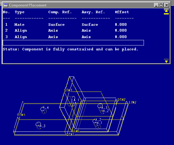
Figure 8.
As you can see from Figure 8, the constraints are listed in the component placement window. Also, the component placement window will tell you if you have enough constraints to place the part.
Repeat this process until all the parts are assembled as in Figure 8a. Notice that many of the parts are brought in as components multiple times. This is possible because the components only reference the part files. Make sure that you bring in the bolt part four times, one for each hole.
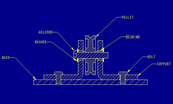
Figure 8a.
The final assembly should look like Figure 9. Save the assembly if you have not already done so.
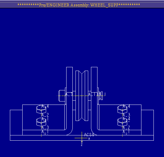
Figure 9.
As you can see, not all the parts are properly sized. Most importantly, the axle rod is too short and does not provide for appropriate clearance with the bushings and pulley. You will have to modify the dimensional constraint values of the axle rod. In order to do so:
Use View>orientation>front and then top to create a view which matches the orientation seen in Figure 8a. Next modify dimensional values:
Modify Dim>click on the axle rod features you want to modify.
The dimensions of the feature will appear. You can modify them as you would modify them in the sketcher mode when creating the part.
When you are done with the modifications. Use the save command and save the part file (not the assembly) of the component you have modified.
This operations may take some practice in order to feel comfortable with. Use the zoom tools and query select to more accurately choose the features to modify.
Once your assembly is complete, you can manipulate the assembly as to have each part a different color. First, to be able to see all the parts, we want to explode our assembly.
To accomplish this, use the following commands from the main menu:
view>cosmetic>explode
Again from the cosmetic menu, choose:
appearances>define
A color definition window will appear. Manipulate the red, green and blue to change the color. Once you have created a color that you like, click on the color itself in the color definition window.
To see the colors that you have created, click on:
show, in the colors menu
A user color box will appear with all the colors that you have created, including white.
To actually change the colors of the individual parts, use the following commands from the colors menu:
set>(click on a color from the user color box)>subassembly>(click on the particular part you wish to change)>done
Continue this process with the rest of the parts in the assembly.
If your part does not change color after you click on done, try the repaint command in the view menu (See Figure 10).
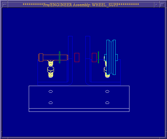
Figure 10.
To see the assembly completely colored in, select shading from the environment menu. (See Figure 11). The tutorial is done. Save the cosmetic changes if desired.
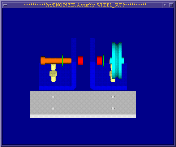
Figure 11.